The left side of the ACE |
The English call this the "near side" and the caption of
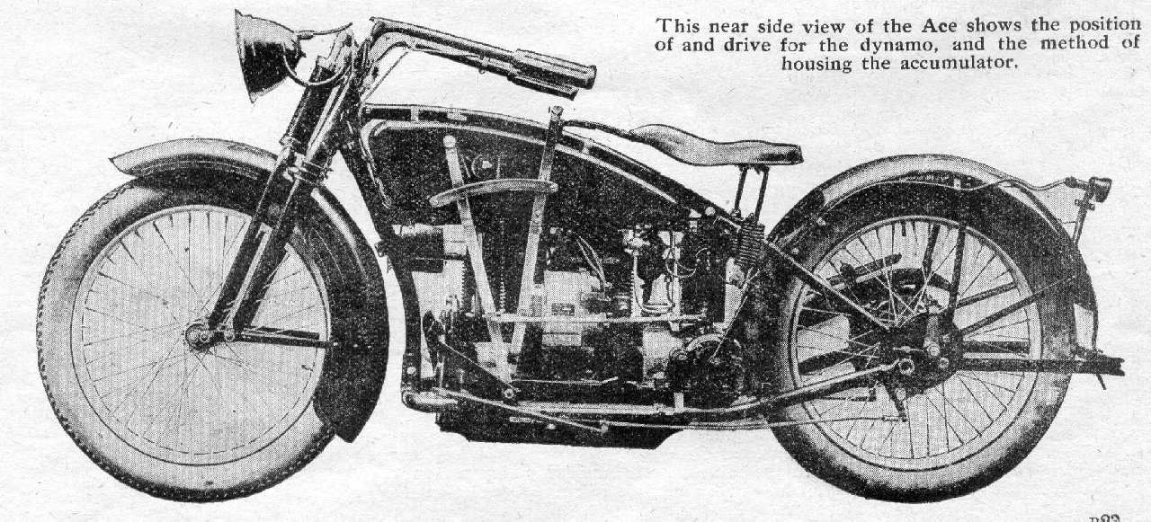
the picture in the magazine states :
This nearside view of the Ace shows the position and drive from the dynamo and the method of housing the accumulator(I appologise for the size of these pictures, but I trust you do not mind a little sideways scrolling to get the details) |
| In this pictute the use of the Berling magneto is clearly shown.
The Splitdorf generator is attached to the tube
underneath the tank by by means of a clamp to the frame and a band around the generator. In this way
the tension of the round drive belt is easily adjusted.
The Splitdorf takes its drive through a small bakelite (approx 45mm dia) pulley and the drive is through a split pulley approx 90mm da. clamped around the driveshaft of the magneto. |
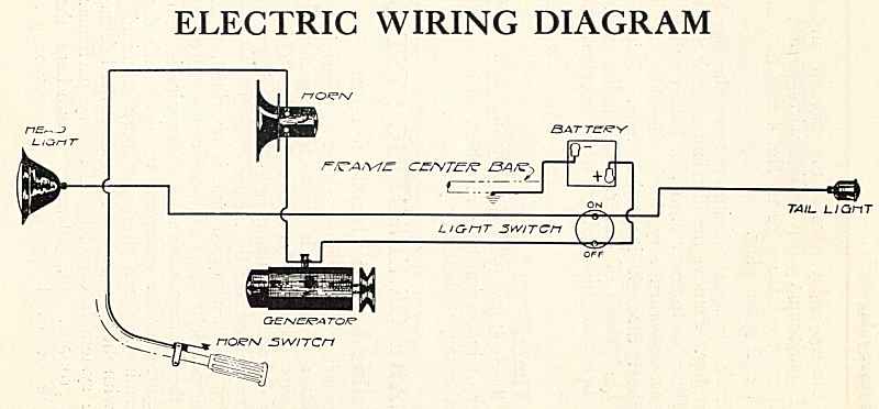 |
| The switch on the battery box is for turning the lights on and off. The horn has voltage all the time.
One accept that the circuitry around the Splitdorf DU-5
did not need any "on - off" battery control as it has a built in mechanical device which would
exclude the need to adapt a traditional solenoid with the dynamo. Check out Steve Blanchard's very informative pages on the Splitdorf generators |
| Return to 1920 Ace presentation |